


Free Samples Available
Qualified projects can receive free product samples
Qualified projects can receive free product samples
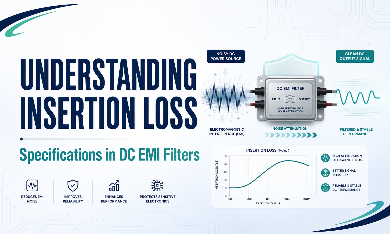
Insertion loss is the first number engineers look for to evaluate the effectiveness of a DC EMI filter. It is a prominent feature on every datasheet and provides an immediate answer to the query: How much noise can this filter block at a certain frequency? It is a problem that the term insertion loss, as described on the majority of datasheets, is a description of filter behavior under monitored test conditions that don't always correspond to the actual environment in which it will operate. Engineers working on DC power motors, systems,s or other applications that have high impedance. The gap between specifications and actuality is the reason problems arise for projects. Knowing how the term insertion loss is described and what it doesn't contain, and the best way to make use of datasheet numbers in a smart way, is crucial to choosing the best DC EMI filter. A reputable EMI filter company will verify that the specification number can be used as a reference point, but not a definitive decision. The term insertion loss refers to the proportion that is reaching the load that does not have a filter installed, as compared to a filter that is present within the circuit. It is expressed in decibels. The higher the value of insertion loss for a specific frequency implies more noise reduction at that frequency. It is a simple formula, and the idea is easy to grasp. It is not as obvious as the fact that insertion loss isn't an inherent property of the filter on its own. It's an attribute of the filter along with the source's impedance and load impedance. If either of them is changed, either of them, and the insertion loss curve alters, often dramatically. The vast majority of EMI filter datasheets provide the insertion loss that is measured using a 50 ohm source and 50 ohm loads. This is the norm that's defined within CISPR 17, the international method of measuring EMI loss in the insertion of filters. This arrangement of 50/50 ohms can be replicated, is quick to determine, and allows an easy comparison of products made by diverse manufacturers. From the standpoint of standardization, this arrangement makes sense. From a practical standpoint, a practical DC power system is usually a bad match. A battery-powered or DC-DC converter power supply will rarely have an impedance of 50 ohms for the source. DC bus impedances of the source are usually lower at low frequencies. They rise in frequency when parasitic elements begin to be activated, and can vary greatly based upon the topology of the converter, the output capacitor, and the control bandwidth. The filter that is placed between the source and the downstream load operates in a totally different context than that used for the creation of the curve in the datasheet. Impedance incompatibility isn't just that the filter is higher or lower than the information sheet suggests. The worst-case scenario is that the filter could generate insertion gain at specific frequencies, not insertion loss, which means it increases certain elements of noise instead of reducing their impact. It is because most practical EMI filters have resonant structures. Inductors and capacitors within LC filter topologies produce resonance frequencies where transfer and storage of energy shift dramatically. When operating under the controlled 50/50 Ohm tests, they are slowed by the load and source impedances so that they keep the insertion's gain small or unnoticeable. If the same filter is used in an application with a small source impedance, which is typical in the output of the DC converter, the damping effects are diminished,d and the resonance peak gets much more prominent. The frequency at which the insertion gain is observed can change to the point that it actually creates a substantial background noise. If engineers are recommending the DC EMI filter for switching power supplies or an electric vehicle drivetrain application, it is a real-world failing mode, not an issue of theoretical origin. An EMI filter properly specified in accordance with the datasheet attenuation could make the emission worse within a certain frequency band when it's installed in the system. With these limitations, the challenge is, how can we extract relevant information from specifications for insertion loss when reviewing the effectiveness of a DC EMI filter? The initial step is to find the primary spectrum of frequencies that are used for the particular application. Harmonics in the switching process constitute the main reason for the conductivity in the vast majority of DC power systems. In the case of a converter that is operating at 100 kHz, the conducted emission range that starts at 150 kHz would record the harmonic that is first,t, and the ones that follow that. The definition of insertion loss is crucial in this frequency band for this particular purpose. The third process is to calculate the actual loads and source impedances the filter can see when it is in use. On the side of the source, the output impedance of the converter upstream and the power source will be the most important measure. For load input impedance, downstream equipment plays a role. There is no such thing as 50 ohms for most DC applications. But knowing the difference between them being significantly more or less than 50 ohms will give the ability to determine how much the curve of datasheets will exaggerate or underestimate the real value. 3. Look for a datasheet for filtering that provides more insertion loss curves than the typical 50/50 ohm measurement. Certain EMI filter producers, specifically those that serve the industrial and power electronic markets, provide data for measurements in high-impedance sources or low-impedance load conditions. These curves can be significantly more reliable in predicting the behavior of the real world when used in DC applications, and provide an accurate description of the item. Also, be aware of the insertion loss pattern in the lower end of the frequency spectrum. Filters that show an area of insertion gain on the datasheet for a 50/50ohm chart, even a modest one, indicate that the resonance of the circuit that filters it could be more noticeable under various impedance settings. For sensitive components, this requires further study before defining the part. The specifications for insertion loss of the DC EMC filters aren't bogus. They're part of a standard measurement method that is focused on consistency and reliability. What they don't provide in their own way is an accurate estimation of how the filters would work in a particular DC power system that has its unique loads and source impedances. The organizations and engineers who achieve the highest results out of EMI filtering will be those who can identify the difference between the specifications and the actual application, ask the appropriate questions regarding resonance behaviour, and collaborate with vendors that can work in impedance match rather than only quoting attenuation numbers. BLA Etech brings exactly this kind of knowledge in DC EMI filter design and design, which helps engineers to move beyond datasheets to reliable performance in real-world conditions with confidence.What Insertion Loss Actually Measures and Why the Test Conditions Matter
How Impedance Mismatch Changes Filter Behavior in DC Applications
Reading Datasheet Specifications More Usefully
Conclusion


