


Free Samples Available
Qualified projects can receive free product samples
Qualified projects can receive free product samples
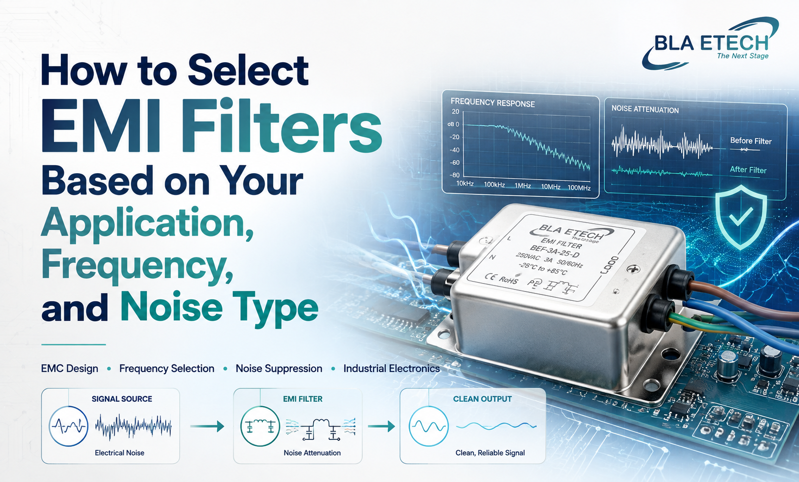
The choice of the best EMI filter is among the decisions in engineering that appear at first glance to be simple. The filter is placed between the source of power and the equipment. It blocks out the sound. The job is done. In reality, the procurement and engineering teams often select filters that are not performing well on their own, not because good filters aren't available; however, the decision was based on insufficient factors.
The three factors that determine if a common-mode EMI filter or one of the Inline EMI filters is appropriate to a particular situation are the type of noise, the frequency profile, as well as the particular mechanical and electrical constraints of the environment it is expected to be operating within. Making any of these incorrectly results in a filter that is either unable to address the noise issue and creates additional problems because of an impedance mismatch or is damaged in a hurry under conditions that the filter was not designed to be used in.
This article explains the process of selection in a systematic manner, so that tech buyers and engineers can transition from the symptom to the specification confidently.
The most frequently encountered point of problem during EMI filter selection is going right to a particular product, instead of first defining the type of noise to be squelched. Filters that are specified without knowing the cause of noise are picked on the wrong foundation, and the insertion loss numbers from a datasheet provide little information about the actual performance of the filter if its structure is not in line with the type of noise.
The EMI noise that is generated by power electronics can be classified into two broad categories, and both require different structural filters.
The noise of the Differential Mode is generated when the line meets neutral conductors. It's caused by switching transients, the ripple current that occurs in capacitors and inductors, and through the majority of power conversion topologies in their switch cycles. The current generated by differential mode noise runs both ways on both supply conductors at the same time; that is what differentiates it from the other type of noise.
Common mode noise moves across the supply and drain conductors at once, returning via the earth path, or via capacitors in the chassis. The cause is the interaction between high-voltage switching nodes as well as the chassis ground via stray capacitances. The common-mode EMI filter targets this particular path through chokes in common mode, which provide high resistance to currents moving through both conductors, while also transmitting differential mode currents without any significant reduction.
The majority of real power systems produce two types of noise simultaneously, and that's why the majority of EMI filters are made to tackle both. The dominant type of noise in a system determines the topology of a filter to prioritize and what component value to weigh during the development.
After the nature of the noise has been recognized, the frequency range of the noise is used to determine the proper design of the filter as well as component size. Conductive emissions standards, such as CISPR 22 as well as CISPR 32 for technology-related equipment as well as industrial equipment respectively, generally span between 150 kHz and 30 MHz. The frequency distribution for the noise in that area varies greatly depending on the application.
In the case of a switching power supply with frequencies that are below 200 kHz, the principal switching frequency as well as its lower harmonics will be the main problem. Filters that address this frequency range require inductors with sufficient inductance at lower frequencies, and capacitors with a high efficiency within several nanofarads up to hundreds.
In high-frequency switching, such as that employed by wide-bandgap semiconductors, such as GaN or SiC devices that operate in frequencies of more than 500 kHz. The noise spectrum expands to higher frequencies, and the filter must maintain its performance in reducing noise further into the frequency spectrum. The parasitic effects on filter components can be a problem. Inductors that are efficient at 150 kHz may show substantial self-resonance over 1 MHz. Once it reaches that point, it ceases to reduce the noise.
BLA Etech's design approach to filter design takes into account components that exhibit parasitic behavior throughout the entire operating frequency band, which is the reason insertion loss curves of BLA Etech filters are recorded and released over the appropriate frequency range rather than merely at one frequency of reference. The form of an insertion loss curve over the entire range of frequencies is much more valuable as a specification tool as opposed to a simple attenuation curve.
An Inline EMI filter sits directly within the power line between the power source and load. It is a term that refers to an actual configuration, not the type of noise, and the inline filter can deal with common mode noise as well as differential mode noise or both based upon its inner topology.
The software environment is used to determine a range of useful selection criteria that go beyond the attenuation capability.
The current rating is perhaps the most evident. The filter has to be calibrated to the highest continuous current generated by the load, that is, with the proper derating of the temperature at which it operates in the enclosure. An inline EMI filter running at the maximum current rated within a temperature-sensitive enclosure may surpass its thermal design limit, which can affect the performance of components and decrease the service life.
Voltage rating requires similar attention. Filters that are rated for single-phase standard mains voltage in a particular market might not have the appropriate rating for industrial supply voltages higher than that in a different one. The voltage rating must be able to accommodate both the nominal supply voltage and transient overvoltages that are experienced in the particular location.
Leakage current can be a commonly neglected specification, especially when safety regulations set limits for earth leakage current. The Y-capacitors of the Inline EMI filter pass an insignificant amount of current to the earth to perform their noise-filtering capability. For medical devices, the leakage current is constrained by standards like IEC 60601. For consumer goods, they interact with the threshold for tripping of devices that generate residual current. The use of a filter that does not check its leakage current in relation to the specifications of the device is the most common cause of difficulties with system integration.
The mechanical form factor, the connection configuration, and design determine if the filter will be built into the system's architecture. If you are looking for a compact device that has limited space, the chassis-mount type of filter could be preferable to one mounted via-hole on a PCB, even though all electrical requirements are equivalent.
Different categories of applications produce different common mode noise profiles, and the Common mode EMI filter choice should be based on the source impedance as well as the noise volume pertinent to the particular use.
Variable-speed motor drives produce substantial common mode noise due to the high dV/dt switch of the output stage of an inverter. The common mode currents that are generated are able to flow through cables and cause disturbances at a significant distance from the driver. Common mode chokes on the output of the drive, along with the input filter, are usually required to tackle the specific path of noise.
DC power sources, which include battery-powered systems and bus designs with 48V that are becoming utilized in automotive and telecom applications, offer a completely different common-mode noise system from AC mains-based applications. The reference to impedance to measure common mode noise in the DC system is usually the ground for the chassis instead of an earth from the mains, and the selection of filter components must take into account the fact that this is the case.
Control systems for industrial applications that have lengthy cable runs connecting fields and control devices are subject to noise coupling in common mode between adjacent power cables as well as switching devices. When these systems are used, common mode filters have to function with a lower frequency than small power supply devices since cable coupling is known to create noise at the lower portion of the frequency range for conducted emissions. spectrum.
BLA Etech designs application-specific common-mode EMI filter solutions to Motor drive, DC power, as well as industrial control,using the particular requirements and noise measurement of the system rather than using a general methodology of catalog selection.
Engineers who go through the steps below when choosing EMI filters can avoid the vast most common pitfalls in specification that cause underperforming filters used in manufacturing systems.
The first step is to start with noise characterisation before selecting a filter. Analyze or recreate the emissions spectrum of your circuit prior to defining the filter. Understanding whether the predominant frequency is in either differential or common mode, as well as where within the spectrum do the emissions that are worst case occur will make any subsequent decision more precise.
The topology of the filter should match the predominant noise type. Filters designed specifically to reduce the noise of differential modes will only provide a slight improvement when the primary noise source can be described as common mode. Verify that the filter's inner topology matches the type of noise determined in the characterisation phase.
Check compatibility with the application prior to signing a contract with a particular component. Make sure the current rating is checked using thermic derating, voltage ratings against the environment of supply fluctuations and leakage current in relation to the safety specifications of the application, and the mechanical form factor against the mounting space and restrictions.
Demand insertion loss data over the entire frequency spectrum instead of settling for a simple headline figure of attenuation. A filter's frequency response decides the extent to which it can actually reduce the frequencies of noise that are responsible for the problems. A single information point is not sufficient information for making an accurate assessment.
EMI filter selection that is done properly is a methodical process, not just a lookup in a catalog. Knowing the type of noise and the spectrum of frequencies and comparing the topology of the filter and the specifications to the operating environment creates filtering that is reliable from day one and does not require modification after testing for compliance.
BLA Etech supports engineers with the process of selecting filters by providing specific guidance for each application, loss of insertion across all relevant frequencies, and design of filters which take into account the actual operational conditions of the system. It doesn't matter if the need is a common-mode EMI filter to be used with the variable speed drive, or an Inline EMI filter for industrial machinery, or a customized solution to a particular power system; working with the application's data instead of catalog standard settings consistently yields better results. One of the most effective first steps is a thorough understanding of the noise-related issue that the filter must solve.


