


Free Samples Available
Qualified projects can receive free product samples
Qualified projects can receive free product samples
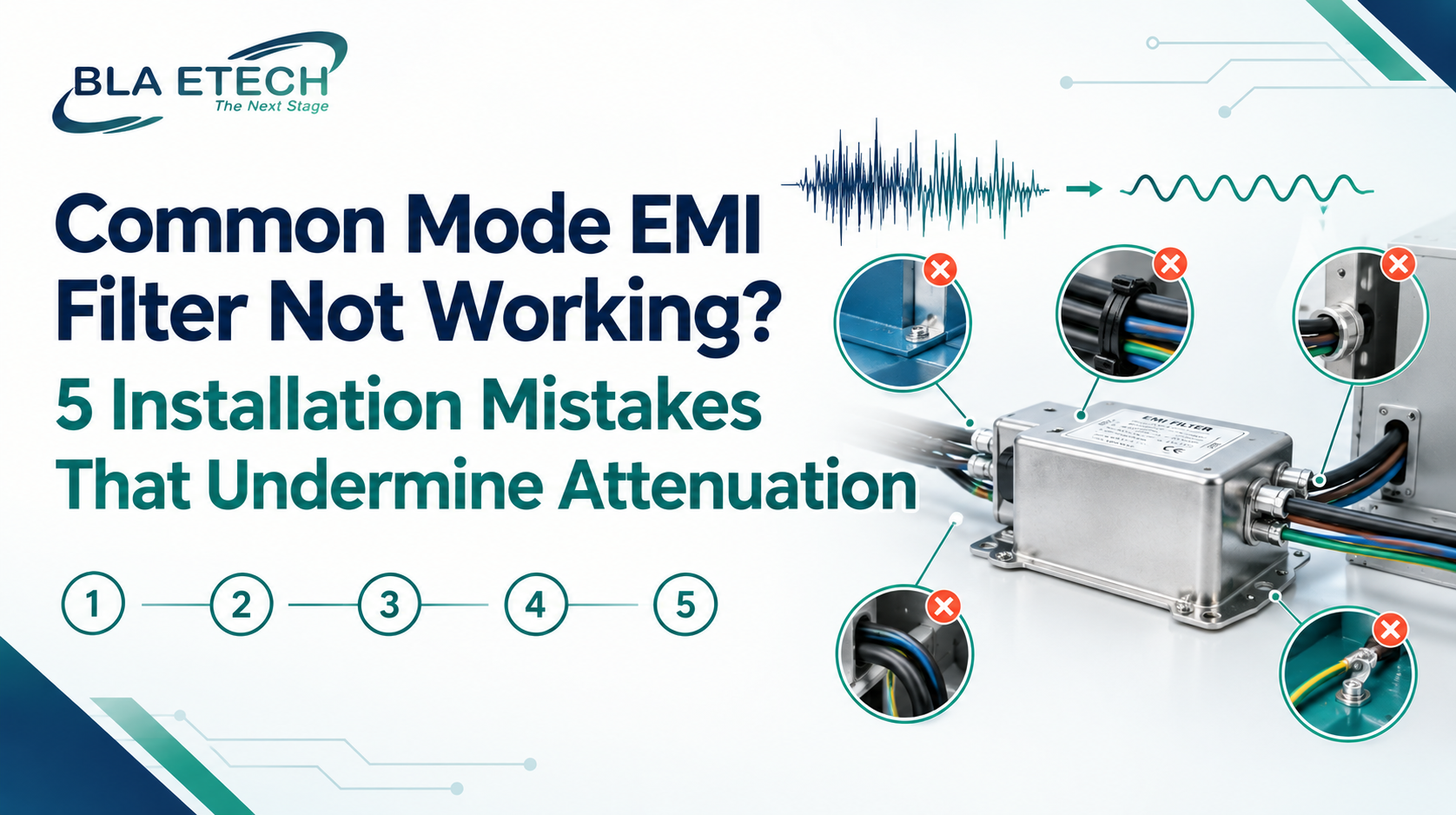
Few things frustrate an engineer more than a common mode EMI filter that looks right on paper and still fails the emissions test. The voltage matches, the current rating has headroom, and the datasheet shows healthy attenuation. Yet the noise is still there. In most of these cases, the filter isn't defective. It's being asked to work in an installation that quietly takes away its performance.
The same is true for a DC EMI filter sitting on a battery bus, a DC drive, or a control panel supply. A well-made EMI filter can only attenuate noise that is actually forced through it into a solid ground at the right point in the system. Here are five installation mistakes that undermine that and how to fix each one.
A common mode EMI filter works by diverting noise to ground through its Y-capacitors. That makes the ground connection part of the filter itself, not just a safety wire. If the filter is bolted to a painted or anodized panel, or grounded through a long wire lead, the path to ground becomes high impedance at the exact frequencies you're trying to suppress. The noise has nowhere good to go, so it carries on down the line.
The fix is simple but often skipped. Mount the filter on bare, clean metal with a short, direct bond to the chassis. Even a compact single-phase part like BLA Etech's BL2010-01-F, built for general-purpose applications, can only deliver its rated common mode performance when its case and ground terminal have a low-impedance path to the enclosure.
Many designs place the filter close to the equipment it protects, which feels logical. But an EMI filter should sit where the cable enters the enclosure. If unfiltered power wiring travels several centimeters through the enclosure before reaching the filter, that wiring acts as an antenna, radiating noise inside the box and coupling it onto everything nearby, including the clean side of the filter.
For higher-current systems, this matters even more. A three-phase part like BLA Etech's BL358-16-T, rated 480VAC at 16A with Class C1 and C2 compliance, is designed to clean the incoming supply. Placing it right at the entry point keeps the unfiltered section as short as possible, which is where most of the benefit comes from.
This one deserves its own place because it's so easy to miss. When the filter's input and output leads share a cable bundle, or run parallel for any distance, high-frequency noise can jump from the dirty side to the clean side, bypassing the filter entirely. The test result looks exactly like a weak filter, so people replace the part instead of fixing the routing.
Keep input and output leads physically separated, ideally on opposite sides of the filter, and cross them at right angles if they must cross. If separating the wiring lowers your emissions on a quick retest, the filter was never the problem.
Insertion loss curves are measured in a standardized test setup with fixed source and load impedances. Your real system rarely looks like that. Actual source and load impedances change with cable length, converter behavior, and load conditions, and the attenuation you see in the field can differ noticeably from the published curve, especially for common mode noise.
The practical response is to treat the datasheet as a starting point, not a promise. Build in margin, test with the actual cabling in place, and if the margin is thin, talk to your manufacturer about a filter tuned to your real noise profile. This is one of the most common reasons a custom design ends up being the right answer.
A DC EMI filter isn't just an AC filter used on a different supply. Voltage ratings, capacitor types, and current handling all need to be confirmed for DC operation, and an AC voltage rating doesn't automatically translate to the same DC rating. On battery systems, DC drives, and switched-mode DC supplies, this check matters because the noise is often fast, common mode heavy, and continuous.
Always verify the DC voltage and current ratings specifically, and confirm the filter is intended for the DC application before it goes into the design. If you're unsure, ask the manufacturer rather than assuming.
Before ordering a different common mode EMI filter, run through this short list:
Is the filter grounded to clean, bare metal with the shortest possible bond?
Is it mounted at the cable entry point rather than deep inside the enclosure?
Are input and output leads separated and not sharing a bundle?
Have you tested with real cabling and loads, not just relied on the datasheet?
For DC lines, have the DC voltage and current ratings been confirmed directly?
Most failed filter installations aren't failed products. They're small installation details that add up to a lost decibel here and a bypassed path there. BLA Etech works through exactly these questions with engineers, from grounding and placement to whether a standard part or a custom design fits the application better.
If your common mode EMI filter isn't performing the way its datasheet suggests, start with the installation before changing the part. Check the ground, the placement, the routing, and the ratings, and retest. If the problem persists, that's the moment to bring in a manufacturer who can look at your actual noise environment, whether that calls for a standard filter or a custom DC EMI filter built around your system.


